Google Classroom
Google Classroom
GeoGebra
Classe GeoGebra
Se connecter
Chercher
Google Classroom
Google Classroom
GeoGebra
Classe GeoGebra
Contenu
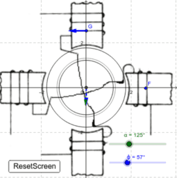
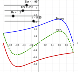
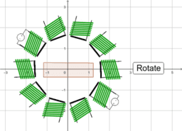
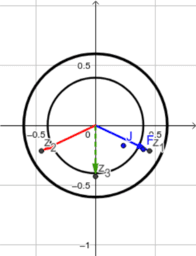
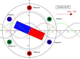
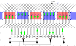
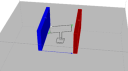
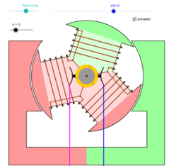
Electrical Machine
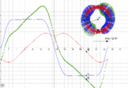
DC: Armature Reaction
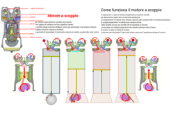
Motore a scoppio
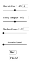
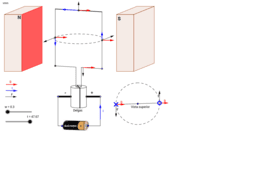
DC Motor
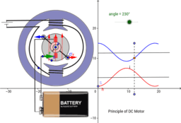
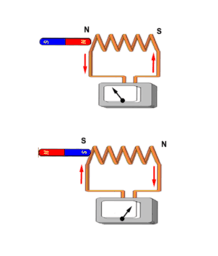
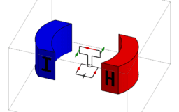
DC: MotorPrinciple
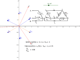
V-Connection01
Tran_AutoTransformer
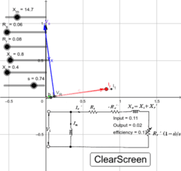
TransformerVectorDiagram
Empty
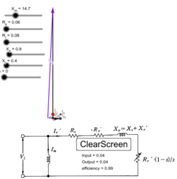
Ind_Induced_Volt_Slip_Example
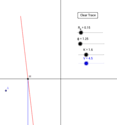
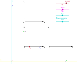
Copy of Geometric Transformations in the Coordinate Plane
DC: Compound Winding
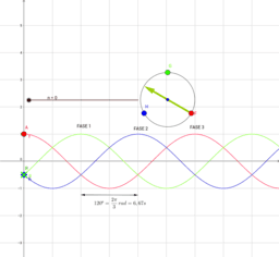
Etc: SingleIndSimpleTwoPhaseAdd
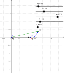
Ind: Induction Motor Vector Diagram
Synch: Synchronization_01
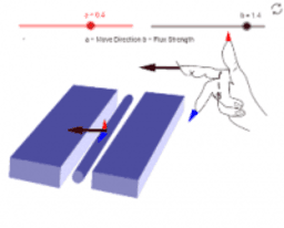
Gen: RightHandTheory
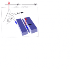
Gen: LeftHandTheory
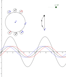
Etc: IndSingle
Etc: SingleIndTorque
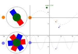
Etc: SteppingMotor
Etc: PulsingFlux
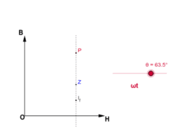
Gen: Hysterisys03
Gen: Hysterisys02
Gen: Hysterisys01
Tran: TransformerNoLoad
Tran: TransformerVectorDiagram
TransformerVectorDiagram
Tran: TransformerLoad
InductionMotorRPI
Trans: Lentz
Ind: CircleDiagram
Ind: Induction Motor Vector Diagram
Ind: VelocityControl
Ind: TorqueSimple
Ind: TorqueSimple
Synch: Induction Relative Rotation
Synch: Induction Rotor Frequency
Synch: Parallel Connection
Synch: Synchronization
Synch: Amateur Reaction
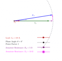
Synch: PowerAngle_Motor
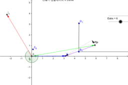
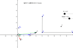
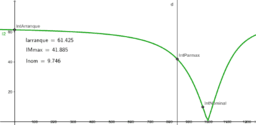
Synch: VCurve_Motor
Synch: VCurve_Motor_01
Synch: VCurve_Motor
Synch: E=V+IsRs Graph (Generator)
Synch: Rotating Flux
Synch: Distributed Winding
Synch: Short Winding
Synch: Generator Principle
DC: Self Excite
DC: Velocity Control
DC: Torque Curve
DC: Wave winding
DC: Velocity Control
DC Commutator
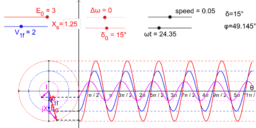
TransformerInducedEs
CTKongjuClass
ctutest
Synch: Parallel Connection
Synch: Power Angle Generator
Synch: Random VCurve Motor
Synch: VCurve Generator
Synch: Electromechanical Rotation
Synch: Open short experiment
Sync01
Design for a trifasic motor brushless
Design for a trifasic motor brushless
Kondenzátor a váltóáramú áramkörben - fázisviszonyok
Motor trifàsic asincrònic
Electrical Machine (Distributed Winding)
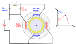
Single phase motor start
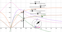
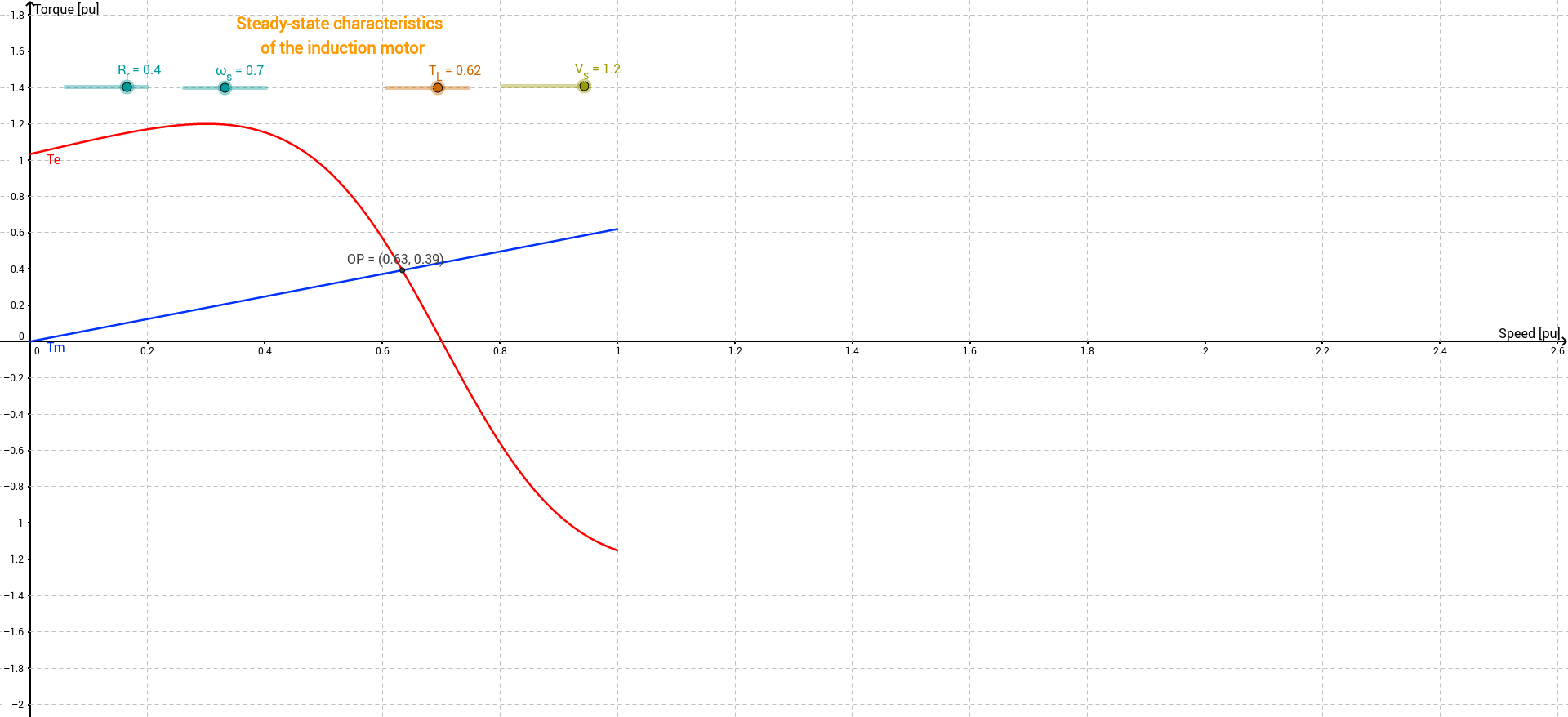
Steady state characteristics of Induction motor
Hysteresis
Flux plots and B-field distributions
Armature mmf waves: Sinusoidal windings
hysteresis0
Phasor diagram of synchronous machine and sinusoids
Potier diagram for the synchronous machine
Magnetic field in a wound rotor induction motor
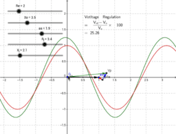
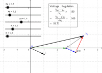
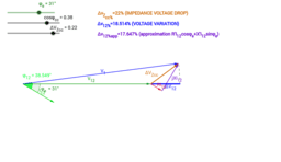
Transformer voltage variation from no-load to load operation
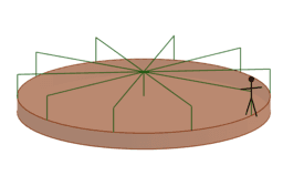
Person on a Rotating Platform
Magnetic Induction
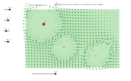
Electric Field Vectors
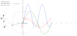
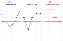
Position, Velocity, and Acceleration vs. Time Graphs
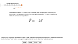
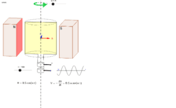
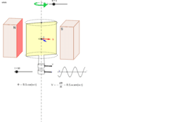
Simple Harmonic Motion Tutorial
Simple Harmonic Motion Optical Illusion
Caratteristica meccanica motore asincrono trifase
Gràfica corrent alterna
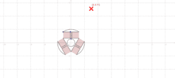
DibuixPlantillaMotor3B
DibuixPlantillaMotor3B
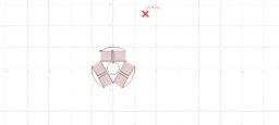
Dibuix Plantilla Rotor 3B
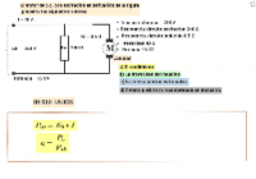
Problema TIPO motor serie corriente continua
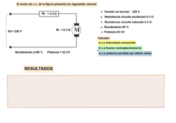
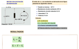
Problema tipo motor derivación CC
Motor cc en derivación problema tipo
Magnetismo. Motor eléctrico.
Motor
Ejemplo motor en derivación
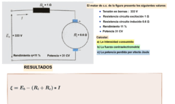
Problema tipo de motor con excitación serie
Motore elektrikoa
Motore Elettrico
Elektromotor
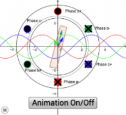
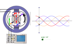
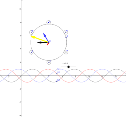
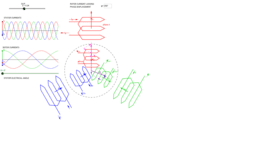
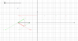
Rotating variables (U, I, Flux) in 2-phase AC motors
3-phase vector variable in 3D space
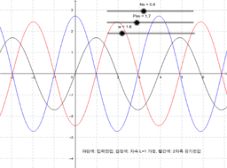
Rotating variables of 3-phase AC motors
Alternador
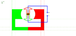
Funktionsweise eines Gleichstrommotors
Sin título
Motor asíncrono / induction motor
Synchronous Generator Terminal Voltage
Copy of Phasor Diagram for Load Condition of Synchronized Generator
Phasor Diagram for Load Condition of Synchronized Generator
Capabilities Diagram
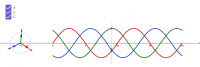
Three phase sum
Rotating Field
3 Phase Line and Phase Voltages
Counter-rotating Fields
Three Phase Phasors
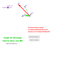
Ggb-SL-Machine Synchrone angle de décalage interne
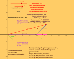
Ggb-SL-Diagrame synchrone MS (PQ)
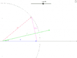
Machine synchrone à excitation constante couplée au reseau
Electrical Machine
Auteur :
shamlou
Electrical Machine
DC: Armature Reaction
Motore a scoppio
DC Motor
DC: MotorPrinciple
V-Connection01
Tran_AutoTransformer
TransformerVectorDiagram
Empty
Ind_Induced_Volt_Slip_Example
Copy of Geometric Transformations in the Coordinate Plane
DC: Compound Winding
Etc: SingleIndSimpleTwoPhaseAdd
Ind: Induction Motor Vector Diagram
Synch: Synchronization_01
Gen: RightHandTheory
Gen: LeftHandTheory
Etc: IndSingle
Etc: SingleIndTorque
Etc: SteppingMotor
Etc: PulsingFlux
Gen: Hysterisys03
Gen: Hysterisys02
Gen: Hysterisys01
Tran: TransformerNoLoad
Tran: TransformerVectorDiagram
TransformerVectorDiagram
Tran: TransformerLoad
InductionMotorRPI
Trans: Lentz
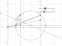
Ind: CircleDiagram
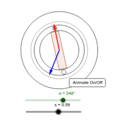
Ind: Induction Motor Vector Diagram
Ind: VelocityControl
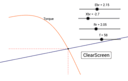
Ind: TorqueSimple
Ind: TorqueSimple
Synch: Induction Relative Rotation
Synch: Induction Rotor Frequency
Synch: Parallel Connection
Synch: Synchronization
Synch: Amateur Reaction
Synch: PowerAngle_Motor
Synch: VCurve_Motor
Synch: VCurve_Motor_01
Synch: VCurve_Motor
Synch: E=V+IsRs Graph (Generator)
Synch: Rotating Flux
Synch: Distributed Winding
Synch: Short Winding
Synch: Generator Principle
DC: Self Excite
DC: Velocity Control
DC: Torque Curve
DC: Wave winding
DC: Velocity Control
DC Commutator
TransformerInducedEs
CTKongjuClass
ctutest
Synch: Parallel Connection
Synch: Power Angle Generator
Synch: Random VCurve Motor
Synch: VCurve Generator
Synch: Electromechanical Rotation
Synch: Open short experiment
Sync01
Design for a trifasic motor brushless
Design for a trifasic motor brushless
Kondenzátor a váltóáramú áramkörben - fázisviszonyok
Motor trifàsic asincrònic
Electrical Machine (Distributed Winding)
Single phase motor start
Steady state characteristics of Induction motor
Hysteresis
Flux plots and B-field distributions
Armature mmf waves: Sinusoidal windings
hysteresis0
Phasor diagram of synchronous machine and sinusoids
Potier diagram for the synchronous machine
Magnetic field in a wound rotor induction motor
Transformer voltage variation from no-load to load operation
Person on a Rotating Platform
Magnetic Induction
Electric Field Vectors
Position, Velocity, and Acceleration vs. Time Graphs
Simple Harmonic Motion Tutorial
Simple Harmonic Motion Optical Illusion
Caratteristica meccanica motore asincrono trifase
Gràfica corrent alterna
DibuixPlantillaMotor3B
DibuixPlantillaMotor3B
Dibuix Plantilla Rotor 3B
Problema TIPO motor serie corriente continua
Problema tipo motor derivación CC
Motor cc en derivación problema tipo
Magnetismo. Motor eléctrico.
Motor
Ejemplo motor en derivación
Problema tipo de motor con excitación serie
Motore elektrikoa
Motore Elettrico
Elektromotor
Rotating variables (U, I, Flux) in 2-phase AC motors
3-phase vector variable in 3D space
Rotating variables of 3-phase AC motors
Alternador
Funktionsweise eines Gleichstrommotors
Sin título
Motor asíncrono / induction motor
Synchronous Generator Terminal Voltage
Copy of Phasor Diagram for Load Condition of Synchronized Generator
Phasor Diagram for Load Condition of Synchronized Generator
Capabilities Diagram
Three phase sum
Rotating Field
3 Phase Line and Phase Voltages
Counter-rotating Fields
Three Phase Phasors
Ggb-SL-Machine Synchrone angle de décalage interne
Ggb-SL-Diagrame synchrone MS (PQ)
Machine synchrone à excitation constante couplée au reseau
Suivant
DC: Armature Reaction
Nouvelles ressources
apec
z`]]
רישום חופשי
seo tool
Nikmati Keunggulan Di Bandar Judi Terpercaya
Découvrir des ressources
Complex analysis: circle of convergence
Perpendicular Criteria
Two lines intersected by a Transversal Activity 2
Cone & Cylinder by Revolution'in kopyası
Line equidistant from 3 points
Découvrir des Thèmes
Algèbre
Distributions
Pythagore ou Théorème de Pythagore
Fonctions Affines
Plans