Field oriented control of a short circuited slip-ring asynchronous machine (induction machine)

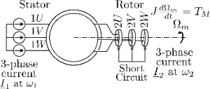
In this animation the stator (three phase symmetrical winding, phase width , terminals 1U, 1V and 1W) is fed by a three phase current. The slip-ring rotor (three phase symmetrical winding, phase width , terminals 2U, 2V and 2W) is short circuited. The induced voltages (emfs) in the rotor are calculated using Faraday's law of induction: with the coupled magnetising fluxes with the rotor phases. The rotor currents are calculated from the equivalent RL rotorcircuit for each phase: solved for . The (changing) impressed stator currents together with the (changing) induced rotor currents form the (changing) resulting mmf field (which is then used again to calculate the emfs in the rotor phases...). The indirect method is used for field orientation in this animation: "In the indirect methods for field orientation, synchronisation is obtained by means of the slip equation, which is indeed a necessary and sufficient condition for field orientation. From the desired q- and d-axis current components, the required slip frequency () is calculated with a slip calculator. This slip frequency is then combined with the measured rotor speed or angle to obtain the required stator frequency and phase. Variations of the torque producing current component cause a change of the torque proportional to this current variation (without any further transient); variations of the flux current component are accompanied with a transient determined by the field time constant (as the laws of physics prohibit any sudden changes of induction or flux)." [Electrical Machines and Drives - J. A. Melkebeek] Brown and pink waveforms are the current densities and (A/m) of stator and rotor respectively. It is assumed that the phase conductors are spread very finely/thin over the phase width (), so that the current density is a constant over a phase width. The black waveforms (dashed line) and (dash-dot line) are the accompanying mmfs (Aw) produced by the current densities and respectively (where and symmetry requirements allow to locate the neutral point where ). Please see also: https://www.geogebra.org/m/w2cvs3kd, https://www.geogebra.org/m/azhgwttv and https://www.geogebra.org/m/tny9ykfg. The solid black line is the total mmf of rotor and stator, . The torque resulting from a rotating fundamental field layer and rotating fundamental current layer can be calculated with . In this animation the reluctance of the iron core is neglected so that the air-gap induction in each point of the armature circumference follows directly from the local total mmf of rotor and stator: with and the air gap length. The torques and (produced by the fundamental functions) are given by [Nm]: and with some (machine) constant. In the animation the torques are then given in relation to the maximum attainable torque in the animation [pu]. is assumed (load torque is zero) so that the rotor accelerates/decelerates according to the applied electromechanical torque (i.e. dynamic conditions are animated). Equations of motion were implemented as shown in 'Geogebra Physics Simulation - Tutorial' by Kornél Rokolya (Youtube). Important note: Despite the best efforts of the author, it can be observed that the field orientation is not perfect in this animation: - at lower values of , a variation of does not anymore result in a perfectly proportional variation of the torque, - a transient in the torque can be observed when is quickly changed. Please download the .ggb file and open with the Geogebra Classic 5 application (see https://www.geogebra.org/download) if the animation is too slow in your browser. The animation is designed to be opened on a 1080p screen and with "Make everything bigger" setting of Windows set to 100% (Change the size of text in Windows - Microsoft Support). Any and all feedback is welcome and can be sent to timon.dewispelaere@kuleuven.be.